Dedication 1: David Ferguson, Kevin Darrah & Hari Wiguna
Then I spotted David Ferguson’s tweet (@fergusondavid6) which showed his hashtag scrolling through an 8x8x8 RGB LED cube. Check it out at hsmag.cc/acFkOZ – it blew my mind! I had seen LED cubes before, but never in RGB. I instantly wanted to make one. David pointed me to Kevin Darrah’s website which detailed how to build the cube – hsmag.cc/JGskjM – and my heart sank.

The cube was made using four-legged RGB LEDs, complicated wiring, and lots of resistors. I had recently fallen in love with the WS2812B LED – a chainable LED that the popular Adafruit NeoPixel is based on. These simple LEDs can be chained together requiring only one ground wire, one power wire, then a single wire between each LED for data. But they were flat LEDs and I knew they would not look as good as 5 mm domed LEDs. So, I shelved the idea until I came across Hari Wiguna’s YouTube page: hsmag.cc/nTKrSy.

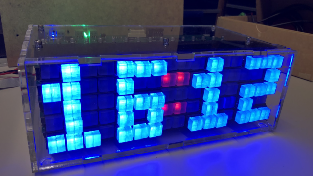
Here, I saw that Hari had already made an 8×8×8 RGB LED cube using WS2812Bs, but more importantly he made the cube using the wiring as the frame and had placed a ping-pong ball on top of every light so it diffused the light, making it stand out better than it would as a flat LED! There also wasn’t a resistor in sight. This was it, this was going to be my cube and I have Hari to thank for the hours, the money, and the blood, sweat and tears I’ve spent on this project!
How not to build an RGB LED Cube
I started to order my equipment from the far reaches of the internet following Hari’s video as a guide. He didn’t give step-by-step instructions, but they were enough to get the project started.
Problem 1: The 2.5 mm galvanised steel wire only came in reels, so had to be cut, then straightened using a drill. It was fun for the first 25 metres. The next 175 metres, not so much.

Problem 2: Ping-pong balls are very difficult to drill manually. Like Hari, we made a 3D-printed jig in which to hold the balls while we drilled them using a hand drill. Waiting on PCBs to arrive from China, I went ahead and drilled four holes in the top and four holes in the bottom of about 100 ping-pong balls. When it got to threading the balls and the PCBs through the wire, everything was crooked and twisting. We knew the columns might not be straight and might need extra supports, but this was way beyond crooked. Wires were twisting round between lights, and entire columns felt stiff and immovable once all eight PCBs and ping-pong balls were threaded on.
To fix this tangling problem, we decided to cut a hole in the bottom of each ping-pong ball, just big enough for the LED to sit in and to rest on the PCB. This way, the holes would not have to be as accurate. However, a drill was not going to give us this perfect hole and the 100 balls I had already drilled were now useless.
So, of course, we had to buy a CNC miller. We got a fantastic one for around £200 which was also a laser engraver. Luckily, my husband is an electronics nerd and a CNC miller was always on his wish list. So now we had an excuse to buy one together. The miller was a godsend.
How we drilled 512 ping-pong balls
This isn’t the easiest thing you can be asked to do – certainly, not the least time-consuming. So to make things easier, the next thing we did was that we…
• Used the miller to drill eight 38 mm diameter holes into two pieces of
A5 wood
• 3D-printed six holders to hold the sides of the jig – you can get the design at hsmag.cc/PImfCD
• Coded one file to drill four holes into each ball: hsmag.cc/gDyYZc
• Coded another file to cut out a single hole into the bottom of each ball: hsmag.cc/CEAxvH
The whole process took about six minutes for eight ping-pong balls. It made a lot of noise and mess, but I think overall it was worth it. We now had a way to perfectly drill 512 ping-pong balls!
Problem 3: You cannot solder onto galvanised steel. We had done several prototype columns to test the length of each column, whether the signal would carry through the wire, whether it would fit in the boot of my car (it doesn’t, hence I now drive my husband’s car), whether it was strong enough to hold eight ping-pong balls and eight PCBs without bending… yet somehow we didn’t notice how difficult it was to solder onto galvanised steel. Solder just rolls off it. This was such a deal breaker. We had spent so much money on ping-pong balls, a CNC miller, 600 PCBs, 600 RGB LEDs. We were halfway through drilling the ping-pong balls. The wire had been straightened and cut for at least 16 columns. A quick plea to Twitter told us that you could use flux to help you solder onto galvanised steel.
And it worked! Phew! Quick save. Until about… 20 columns later, we realised that flux melts PCBs. The first few PCBs we had done were rotting. They still worked but they looked bad. So, we started to wash each PCB with a toothbrush and some flux remover. Our process was now:
Thread eight PCBs and seven balls onto ground and power columns
Thread data wires through
Add flux to every solder point, using a small paintbrush
Solder the PCBs onto the wires
Spray flux remover onto every single solder point
Scrub every solder point with a toothbrush to remove the flux
Test every column
Black Tuesday
When we got to 16 columns, we made a test base to see how everything worked together. This night shall forever be known as Black Tuesday.
My husband wired the test base up and placed eight columns in. Black smoke started to pump out of the base. All eight columns were blown. He fixed the wiring and put another eight columns into the base (why?). He wanted to double-check the wiring, so lifted the base up and it flipped over, crushing and snapping all eight columns. In one evening he had wasted 16 columns – about 20 hours of work.

Dedication 2: Phil Underwood
I couldn’t have done this project without my husband and partner in crime, Phil. He created the PCB files, he coded the 3D files and the miller files. He did the bulk of the soldering of the PCBs onto the wires. He worked tirelessly with me on Cubert throughout early 2018. He never gave up!
Problem 4: The cube would only go red, green, and blue. The problem with your test code only flashing red, green, and blue is that you don’t spot for a very long time that your cube doesn’t have the capacity to turn any other colour! Our maths had gone wrong at some point and the cube did need capacitors. We now had to add one to the top and bottom of every column. A new eighth step in the process above…
Dedication 3: The people of Twitter!
I started to build the cube in January 2018 and didn’t finish it until March. But it wasn’t top secret. I tweeted constantly about my failures and my frustration. There were many times in the project I could have given up. My followers felt like it was a soap opera with suspense, drama, and maybe even a murder. They tweeted their cries of support, frustration, advice, and admiration. This cube was truly a community-built project. I couldn’t have finished it without the support of my Twitter followers, far and wide.

The Future
Cubert does work. It fulfilled all the requirements mentioned at the start. But it was a disaster building it! That’s why I’ve built Cubert2.
Dedication 4: Pimoroni
I wanted to build a more reliable cube, one that would travel well and not need too much upkeep. I found copper-coated iron rods that would be sturdier and easier to solder onto. But to prevent failures, I needed a machine to solder my LEDs onto the PCBs. The cost for this was beyond my budget. Pimoroni stepped up; they redesigned the PCB, got 1027 made, and then soldered the lights on at their HQ in Sheffield-On-Sea. They also added a capacitor to every LED (genius). They did all this, for free. I am so grateful. I have now made Cubert2, Baby Cubert (4×4 ×4) and have plans for micro:Cubert (5×5×5). What a fantastic company.