This first alternate approach is useful when, for example, we need to drill a small number of holes around a circle, often referred to as the pitch circle diameter, or PCD. Some relatively simple maths can be used to generate the X and Y axis co-ordinates needed to drill these holes, and we can mark out those positions on a workpiece, or we can use the dials on a milling machine to move to these positions and drill. We need to know how many holes we require spaced around the circle, and we need to know the radius of the circle. We then use two similar equations to work out the X and the Y co-ordinates of each hole location, relative to the centre of the circle.

For the X and Y co-ordinates, we use the formula seen in Figure 2, where ‘R’ is the radius of the circle, ‘H’ is the hole number, and ‘N’ is the total number of holes. It can be quite tricky if you are out of practice to put this into a calculator or a spreadsheet, so it’s worth double-checking that you get the right result for the first hole. The X co-ordinate of ‘H1’ should be the same figure as the radius of the circle, and the Y co-ordinate should be zero. Using the formula will only return positive values, so it’s important to note that some of the answers are going to actually be negative co-ordinates when you use them in the real world. It can be useful to roughly draw the hole locations as you work them out so that you can tell when co-ordinates are going to flip to being negative. Continuing and solving all the X and Y co-ordinates gives all the information needed to create a circle of holes.
While a spin indexer might give us more flexibility, for creating simple divisions, a 3D printer can be extremely useful to make an object we can use as the reference for indexing. In Figure 3, we have used a 3D-printed octagonal part to create a collar for some 12 mm brass bar stock. We quickly designed and printed the octagonal collar with the inner diameter being a press fit onto the brass bar stock. Using the faces of the printed octagon, we can rotate the circular bar eight times and perform an operation on each face. In this instance, we have used a precision vice to clamp the workpiece. We set the position with the 3D-printed collar using a small riser block between the milling table and the collar, and then milled the small keyways into the bar stock, repeatedly indexing the part by resetting the piece to the next face of the octagonal collar.

Getting in a spin
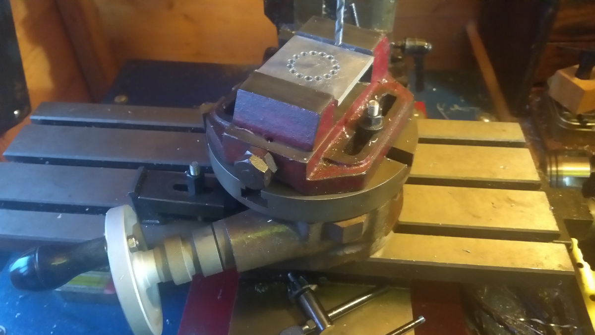
Another workshop item that is a midpoint tool (and not as costly as a dividing head) is a rotary table. A rotary table is a milling accessory that is primarily designed for machining arc paths on the manual milling machine. However, as it can rotate a workpiece through a known number of degrees, it can also be used for dividing purposes. It consists of a circular worktable which is rotated by a gear and worm-gear arrangement attached to a winding handle. It’s a common project for machinists to convert rotary tables into forms of dividing head by adding dividing plates but, even in its standard form, the rotary table can be useful for dividing. In Figure 4, we can see that we have used the rotary table and a vice to create a circle of 15 equidistantly placed holes around a pitch diameter. Simply dialling the table around 24 degrees per index using the graduated dial moves the workpiece to the next position, and a grub-screw on the table acts as a lock to clamp the table while performing the drilling operations.
Using the lathe to divide can be of use, and one job we wanted to create was a dial handle with graduated markings every 36 degrees (so ten marks in a full rotation) – Figure 5. This dial will eventually be part of an assembly that moves the spindle forwards and backwards at a rate of 1 mm per complete revolution. So, marking it with ten marks means each mark equates to 0.1 of a mm movement. We had heard anecdotes of people using a magnetic digital protractor tool to rotate the chuck by a known amount.

The digital protractors are available for less than £15 online, and have a magnetic base so can be attached to ferrous objects. They can be set into a mode where they can be zeroed, and therefore we can repeatedly use them to rotate objects by a known amount. To create this crude but effective marked dial handle, we placed the workpiece in the lathe chuck with the lathe unplugged, and locked the spindle in place. We then used a sharp tool in the tool holder to mark a line into the workpiece by pushing it into the piece slightly and then moving the carriage back out from the workpiece to scribe a line. We then placed the digital protractor on a jaw of the chuck, unlocked the spindle, and hand-rotated the workpiece 36 degrees, locked the spindle, and repeated the process until we had marked all ten lines (Figure 6). While we had some doubts about how well this would work, and we definitely could increase the quality of the mark by grinding a purpose-made tool, we were very surprised at how accurate this method was.

Getting creative
With imagination, hackspace-type tools like laser cutters, 3D printers, and CNC machines can be used to create all kinds of tools that can help with dividing tasks. Printing or cutting dividing plates that can be attached to spindles can enable us to create dividing heads, and we have seen many examples of 3D-printed gears being used to index workpieces.
Taking things a little further, we created a tool that helps us mark divisions around tubular workpieces, which is a common task for those involved in the building of model rockets who want to accurately place fins around a tube. We based this tool around a type of self-centring chuck called a Longworth chuck which consists of two plates which, when counter-rotated, can move four ‘jaws’ inwards and outwards. This assembly allows a tube to be held in position with the jaws either inside or outside of the tube, (Figure 1). Instead of making the bottom plate of the chuck assembly circular, we used Inkscape’s ‘gear generator’ plug-in to create a gear with 60 teeth. We then numbered each gear tooth valley from 0 to 60, to allow us to rotate the assembly by a known amount.

We added a base, and created some sliding gear locks which simply engage with the gear and can lock it in place. The rest of the assembly of this tool consists of a simple pair of stand-offs with a V-shape cut into the top of them, which allows a pen or pencil to be slid into position and mark a dot onto the held tube Figure 7.

Any number of marks that’s a factor of 60 can be made by starting with the gear set to zero at the reference gear lock, and marking the first point and then indexing the assembly around to the desired division. So, for the example of a rocket tube with 4 fins, indexing and marking through the numbers 0, 15, 30, and 45 gives the correct points. Having marked the tube, we can remove it and extend the marks using a piece of aluminium angle to ensure the lines remain straight in relation to the centre point of the tube. While this application is a pretty unusual use case, we hope that it perhaps inspires ideas into how laser-cut or 3D-printed tools can be made that assist dividing tasks in projects. All the files for this particular tool are available here: hsmag.cc/UXcwxP.
If you have your own hackspace-style methods and approaches to dividing and indexing, share them with us here: twitter.com/HackSpaceMag.