You'll need:
Shadow box frame (Amazon #B07BDR94VW)
See-through mirror glass or acrylic (Amazon # B07TWYKGNB)
Black paper tape
Pen or pencil
Ruler or tape measure
Craft knife
USB cable
Adafruit Trinket M0 (Adafruit #3500) or NodeMCU microcontroller (Amazon # B07L8W9SP3)
White alphanumeric LED displays with I2C backpacks (two or three, depending on your size preference and budget) (Adafruit #2157)
Solderless breadboard
Soldering tools and supplies
Large solderable breadboard (Amazon #B07DH7QDWT)
Solid-core hook‑up wire
To get started, first assemble the alphanumeric displays by soldering them to their I2C backpacks. The backpack is a circuit board containing a chip to control each of the LED segments through the I2C data protocol, which uses just two data pins to control the large number of LEDs. The delicate segment display pins go through the holes on the board; then you can lay the display down on its face and solder the pins at the back. Be careful to line up the decimal dot LED with the dot on the board’s silkscreen to avoid soldering it in upside down!
It’s smart to solder two diagonal corner pins first, so you can make any adjustments to the seating before everything’s locked in place. Components with multiple pins are exceedingly difficult to de-solder later. After all the leads are soldered, clip the protruding wire leads with a pair of flush snips. Next, you should solder the included header pins into the labelled row of holes at the top of the display. It’s easier to get everything lined up straight if you do this part of the assembly with the header pins sticking into a solderless breadboard (Figure 1).

You can chain these I2C devices together, so long as they have different addresses. You should change the address of two of the displays by soldering to bridge a set or two of the pairs of pads on the back of the board. For instance, bridge the pads marked A0 on one display, and the pads marked A1 on another, leaving the third one at its default address (Figure 2). You don’t have to use three displays, though! It still looks good and readable with just two, albeit harder to photograph a meaningful phrase since so few letters appear at once.

Test it, no excuses!
Test your displays with a solderless breadboard before assembling them into your project (Figure 3). That way, if something goes wrong, you won’t have to spend a bunch of time trying to test multiple variables at once or have to waste time undoing and redoing work unnecessarily. You can use the alphanumeric display’s Arduino library example code to test each screen individually. The simple code available with this project includes a sketch to scroll a test across three displays at once, which helps with identifying and confirming the correct address for each display.

<b>// label the displays with their i2c addresses

struct {
  uint8_t           addr;         // I2C address
  Adafruit_AlphaNum4 alpha4;

} disp[] = {
  { 0x70, Adafruit_AlphaNum4() },  // left-hand display
  { 0x72, Adafruit_AlphaNum4() },  // middle display
{ 0x71, Adafruit_AlphaNum4() }, // right-hand display</b>Look for this block of code at the beginning of the quadalphanum-multi example. If your displays aren’t scrolling in order, try swapping the addresses (0x70, 0x72, 0x71) and re-uploading your code. If you soldered a different configuration of address pins than pictured, the other addresses you might try are 0x73, 0x74, 0x75, 0x76, and 0x77. The address is calculated as a sum of 0x70 and the bridged address pins, each of which has its own value (A0 = 1, A1 = 2, A3 = 4).
(Solder) smoke and mirrors
Now it’s time to lay out the final circuit on a big perfboard. Align it to one of the bottom corners of your shadow box frame, then place your displays so that they are centred in the frame from right to left, with the help of a ruler (Figure 5). Note which holes in the perfboard align with the display headers, then solder the display headers in place. It’s very important that the displays align with one another such that they will appear as one long seamless display. However, it’s not essential that you solder them in the same order you had them in earlier, since you can always rearrange the addresses in the code.

Solder up the rest of the circuit using solid-core hook-up wire, and make sure it works as expected (Figure 6). You can download the code from hsmag.cc/issue30. Adjust the display I2C addresses if necessary, as you did when testing, so the message scrolls smoothly across all the displays as one.

To assemble the mirror, grab a piece of see-through mirror plastic or glass that is the same size to fit your shadow box frame. You can order this stuff online or find it at speciality plastics and glass retailers. You can use a thick piece of glass or plastic instead of your frame’s glass, or use a thin piece of plastic layered behind the frame’s original glass. Peel away any protective film and assess which side gives the best reflection, since it’s not always the same from both sides. Cover the 'wrong' side of it in black paper tape, or tape some on some dark paper.
Place your frame face-down on your work surface, then install the front glass/plastic panel, with the reflective side facing down. Place your completed circuit in the frame, in the same corner it was when you aligned your displays earlier, and use a pencil or pen to trace (as best you can) the outline where the display meets the mirror surface. Remove the circuit and clean up your tracing with a ruler to create a more precise rectangle that matches the size and position of the alphanumeric displays.
Carefully cut out this rectangle with a craft knife, optionally re-taping the edges of the rectangle to create clean, straight lines (Figure 7). This tape will stop light from bouncing around behind the mirror, which would reduce its reflectiveness. Now light can only shine through where the displays are.

Plug a USB cable into your circuit before replacing it inside the frame, aligning the display with the rectangular tape cut-out. Notice how your USB cable might need to bend sharply to exit the back or bottom of the frame. Align, mark, and cut a notch in the frame’s back panel to accommodate the cable’s exit.
Mirror, mirror (on the wall)
If you want to hang your mirror on a wall, you'll also want to cut a notch in the frame to allow the USB cable to pass through while keeping the frame flush to the wall (Figure 8). Depending on your frame material, this can be achieved with a utility blade or small handsaw.

Once you’ve determined your cable-routing strategy, you can close up the frame. Use more tape to secure your circuit board inside the frame, so it doesn’t slide around. The sandwiching force of the shadow box back panel may be enough to hold your circuit in place, but the tape helps you align it perfectly and provides extra insurance it won’t wiggle out of place later.
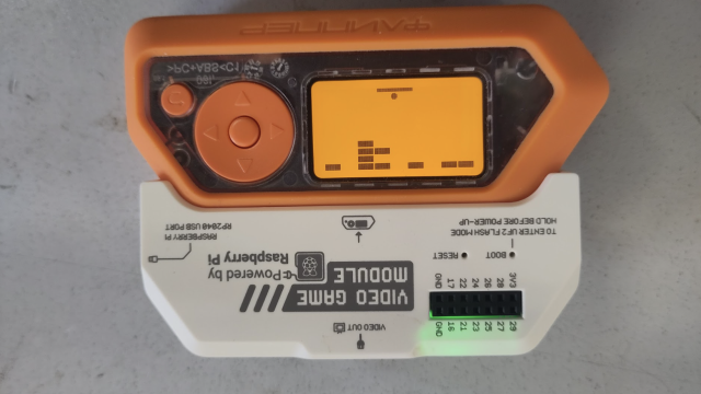
CONTROLLER CHOICES You can decide what microcontroller to use for this project (Figure 4). If you want your mirror to randomly display affirmations from a set list, you can use something simple and offline like an Adafruit Trinket. If you want to try out a more advanced version that connects to the internet to retrieve new messages, you can use a WiFi board like the NodeMCU. Just look up which pins are used for I2C data and clock on your microcontroller and connect accordingly. Additionally, these displays require connections to ground, power, and a reference voltage matching your microcontroller’s logic voltage.